|
X-Ray Powder Diffraction at High Pressure
Diffraction studies at high pressures provide an opportunity to probe the behaviour of the chemical bonding of solids as a function of decreasing inter-atomic separation, without the complications introduced by changing chemistry.
In general, powder diffraction methods at high pressures yield data that is of lower quality than that which is obtainable from the same sample measured at ambient conditions on the same instrument.
When planning a X-ray powder diffraction experiment at high pressure, the angle dispersive technique at a third generation Synchrotron source is the method of choice. Energy dispersive techniques suffer from many experimental difficulties and do often not lead to quantitative results.
Although there are many different experimental setups with different equipment, different procedures and different evaluation programs, the following provides a scheme on how to set up and perform a typical high pressure X-ray powder diffraction experiment. All figures were taken at the high pressure beamlines ID9 and ID30 at the ESRF, France. Part of the pictures as well as some of the descriptions have been copied with permission from Dr. Stefan Carlson, ESRF, form the ID30 website.
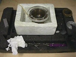
 1. Selection of pressure cell 1. Selection of pressure cell
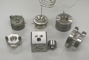
First of all, a suited type of pressure cell must be chosen. For low pressures (up to 6 kbar), large volume gas pressure cells may be used. For higher pressures, there exists a variety of different diamond anvil cells (see Fig.). Most of them are of the cylinder-piston type (LeToullec, Chervin and Diacell) with a gas driven membrane for pressure generation. These cells generally have 0.3 - 0.4 mm culet tips and are thus suitable for pressures up to 50 - 60 GPa. There is also an externally heated DAC for high-PT experiments, as well as a Ruoff/Akahama cell (bevelled diamonds, 0.1 mm culet tips) that can be used in the megabar range
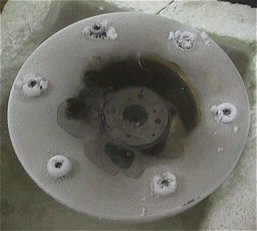
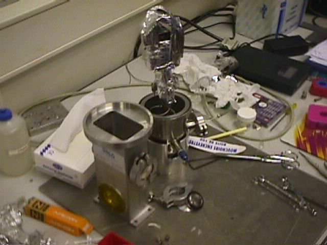
2. Preparation of gasket
The gaskets must be pre-pressed in the empty DAC at moderate pressures.
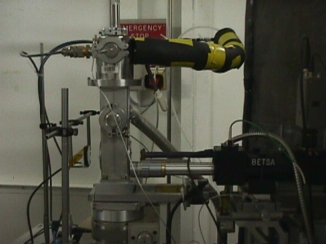
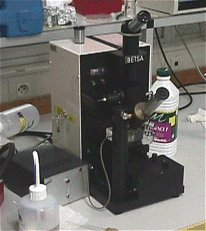 3. Drilling holes in the gasket 3. Drilling holes in the gasket
For drilling the gasket holes, an semi-automatic spark eroder (e.g. Betsa) is useful. Typically W-threads with diameters of 0.1 - 0.2 mm are used in the high pressure lab, but the spark eroder can easily be equipped with thinner threads or conical tips for smaller holes. The gaskets are typically made of stainless steel, 0.2 mm thick, cut for the LeToullec and Chervin cells.
4. Choice of pressure medium and DAC loading technique
Depending on the desired pressure range and the reactivity of the sample, different pressure media (e.g silicon oil, N2, Ar, Ethanol-Methanol mixture etc.) and DAC loading techniques (e.g. cryogenic loading) are available. Silicon oil which can be used up to pressures of 5 GPa must be dried and degassed before using, otherwise air sensitive materials may react or high pressure forms of ice may form which add additional lines to the powder pattern and may cause some confusion.
  Equipment for cryogenic loading of N2 and Ar has been developed for the membrane cells (LeToullec and Chervin), but can probably be used with other types as well. Equipment for cryogenic loading of N2 and Ar has been developed for the membrane cells (LeToullec and Chervin), but can probably be used with other types as well.
5. Choice of pressure standard
There are several possibilities to measure the pressure in the DaC. The method of choice is to use an internal pressure standard like silicon or quartz. The disadvantage of this method is the occurence of additional powder diffraction lines, the advantage is,that the bulk modulus of these standard materials is very well known.
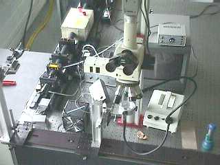
As an alternative, tiny ruby single crystals (spheres) will be placed near the sample. At high pressure, the rubies will be stimulated by strong lase light and their fluorescense spectrum will be measured using a spectrometer. The pressure dependence of a strong fluorescence line will be used for pressure calibration.
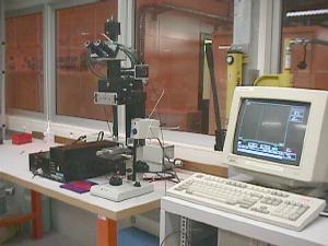 Computer controlled laser spectrometer systems for determination of the pressure by the ruby fluorescence method. Computer controlled laser spectrometer systems for determination of the pressure by the ruby fluorescence method.
6. Alignment of the DAC in the beam
The DAC must be carefully closed. Too much force may already create a high starting pressure, whereas a not completely sealed DAC cannot build up pressure and air sensitive samples might be destroyed.
The well prepared DAC must be carefully centered in the beam.
The detector
Detektor... online image plate readers like the mar345 system....
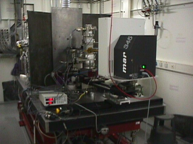 mar345 online image plate reader as installed at beamline ID9, ESRF. mar345 online image plate reader as installed at beamline ID9, ESRF.
 For high pressure experiment at low temperature, ID30 is currently testing an Oxford cryostat with a sample For high pressure experiment at low temperature, ID30 is currently testing an Oxford cryostat with a sample
holder suitable for a DAC. The practical range for the cryostat will be from room temperature, down to 10K.
For high temperature annealing of samples in the DAC a laser system has been built. It consists of YAG and
CO2 lasers coupled to a Nikon microscope.
6. Variation of pressure
The most comfortable way of changing pressure is to use some in situ pressure variation with DAC´s of type ...
Alternatively, pressure must be applied manuall using wrenches, which requires mounting/demounting of the DAC before each measurement.
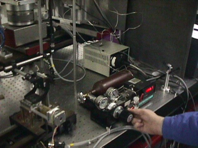 In situ pressure variation system.... In situ pressure variation system....
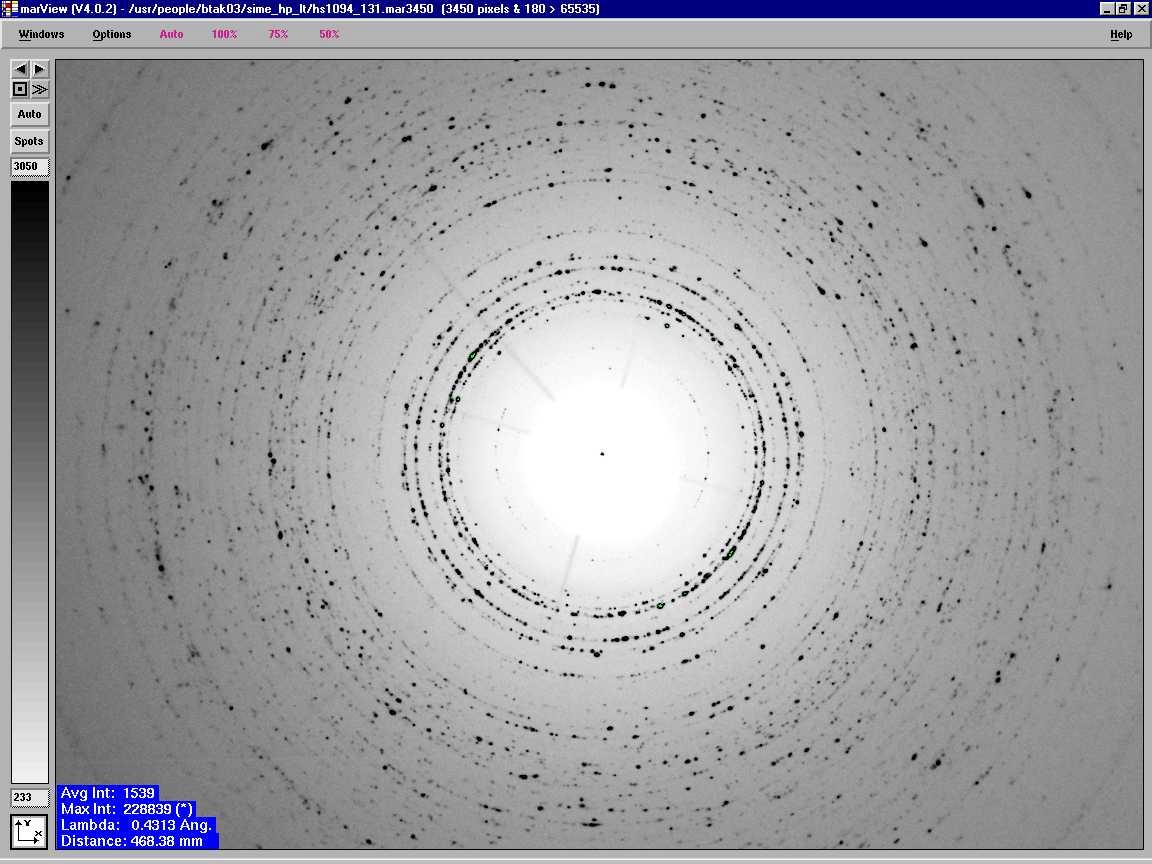
7. Measurement
The exposure time for each frame must be carefully chosen. Due to the limited dynamic range of the image plate,
Typical exposure times for
7. Data reduction
For data reduction and evaluation, a series of free- and shareware programs may be used:
FIT2D by Andy Hammersley (ESRF, France)
The freeware FIT2D is both a general purpose and specialist 1 and 2 dimensional data analysis program, used on most of the European Synchrotron Research Facility beam-lines and by many other crystallography groups throughout the world. FIT2D is used for both interactive and "batch" data processing. Calibration and correction of detector distortions is one of the important uses of FIT2D. Difficult data analysis problems may be tackled using fitting of user specified models. To enable model fitting to be performed on a wide variety of input data, many other more basic data analysis operations are also available. A wide variety of performant graphical display methods are available. The program is available free to academic users and is available by Internet for a wide range of computer systems.
The ESRF website contains all necessary information for downloading and also a comprehensive manual.
Assuming..., the following steps have to be performed in a default run:
- Loading of the image plate data
Appication of a flat field correction using an external correction file (if necessary)
Application of a grid correction using an external correction file (if necessary)
Z-scaling should be set to weak peaks in order to see enough details.
Masking of the beam mask and .... which do not belong to the sample.
This could be diamond single crystal reflections, ruby single crystal reflections, Kossel lines from the diamonds, pressure medium single crystal reflections, scattering from ......
 Correct for center and tilt by....
Integrate ..... selection
Output in GSAS format
Now, some data reduction etc is needed. One suitable shareware to use is:
GUFI by Robert E. Dinnebier (University of Bayreuth, Germany)
All purpose program for data reduction, format conversion, peak fitting, indexing, space group determination and background modelling. GUFI including a short tutorial can be downloaded here
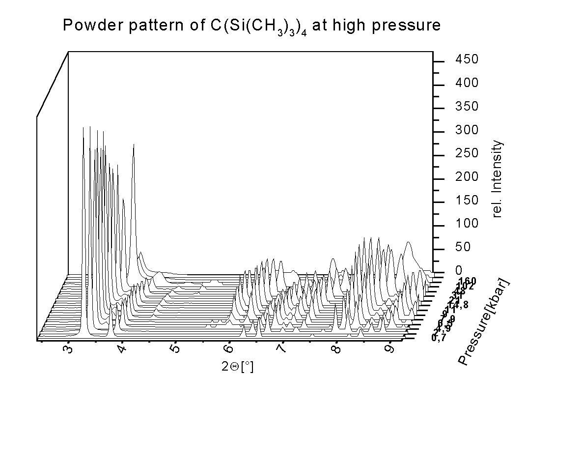 Threedimensional represenation of the pressure dependence of the powder patterns of TC, using the ORIGIN program. The individual data sets have been obtained from FIT2D and bacjground subtracted using GUFI. Threedimensional represenation of the pressure dependence of the powder patterns of TC, using the ORIGIN program. The individual data sets have been obtained from FIT2D and bacjground subtracted using GUFI.
7. LeBail and Rietveld refinement
Le Bail and Rietveld type of fits can be done by using
GSAS by Robert Von Dreele & Alan Larson (LANL, New Mexico, USA)
Download information for the well known Rietveld program including manual and tutorial can be found here. Due to the limited information of a high pressure powder pattern, it is often necessary to use rigid bodies to stabilize a refinement.
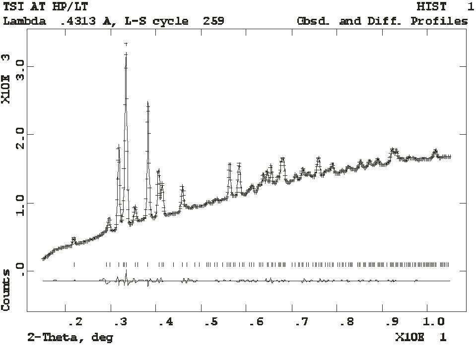 Image plate and LeBail fit of Si(Si(CH3)3)4 Image plate and LeBail fit of Si(Si(CH3)3)4
at 240 K and 2.1 kbar.
(a= 15.380, b= 16.942, c=8.917 Å, = 101.62°,
V= 2275.85 Å3, P 21/n)
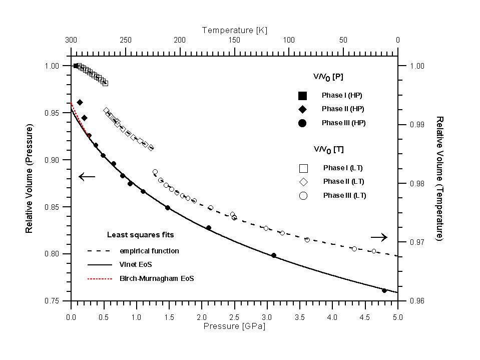
8. Determination of the equation of state
Once the lattice parameters of a pressure series are determined, the equation of state can be calculated by:
EOSFIT by Ross Angel (Bayerisches Geoinstitute, Bayreuth, Germany)
EOSFIT is a least squares program for the analysis of pressure-volume data in the form of Equations of State (EoS).
In the comprehensive manual some important points are reviewed in some detail. Then, a few remarks are made about the refinement of high-pressure powder diffraction data. Finally, a quick review of how to analyse pressure-volume data in the form of Equations of State (EoS) is presented. A sample data set is provided
|