High resolution powder diffraction is, even at synchrotron X-ray sources, time consuming and therefore expensive. Long time experiments suffer, in addition, from any kind of mechanical, electronic and / or source instabilities. The normal setting at the beamline B2 in HASYLAB is a single detector with analyser crystal or soller slits. To increase the efficiency of the measurements we have designed and manufactured a multiple-detector system (MDS) with four analyser units and four scintillation counters based on the Cox [1] parallel beam geometry [2].
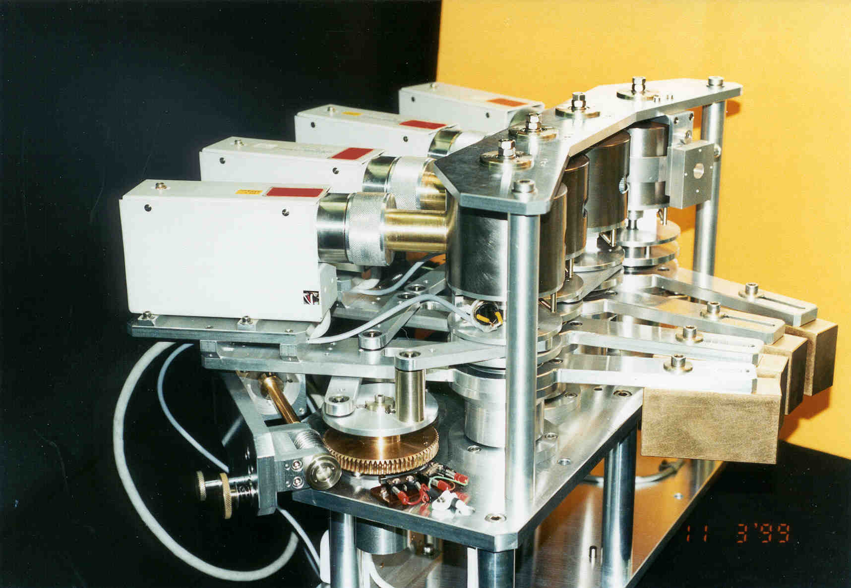
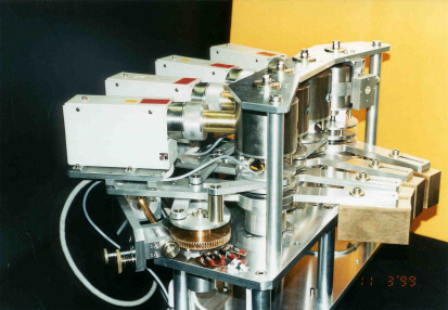 Fig. 1 Multiple-Detector-System;
Enlarged photo JPG-file (128k)
The system consists of exchangeable crystal analysers: four flat Si(111) crystal analysers (0.5 Ĺ < lambda < 1.7 Ĺ) or four Ge(111) channel-cut crystal analysers (1.2 Ĺ < lambda < 2.5 Ĺ) [3]. Using the small divergence of the incident beam the Bragg reflection angles are measured with high angular resolution and independent of the sample position. The efficiency of the system is determined by the net measuring time. The parameters the angular overlap and the angular width of the scans are the essential factors controlling the net measuring time. Different scan configurations will be discussed which provide for a maximum angular overlap of the scans (gain factors up to 3.6) [4] or a maximum width of the angular range. With interval scans reflections are detected only once by one of the four counters: so the gain factor can increased further. One of the main features of the multiple-detector system is the fast adjustment if the wavelength is changed. This opens new ways in detailed measurements at absorption edges.
The X-ray optics of the MDS are illustrated in the schematic diagram of the experimentel configuration for the powder diffractometer B2.
 Fig. 2 Schematic diagram of the MDS
The X-ray beam comes from the storage ring passing the beam line setting (grey box). The mirror focuses the beam on the double crystal monochromator. The wavelength of the primary beam is adjusted with this double crystal monochromator. Slits control the spot of the beam on the sample. After the beam is adapted to the experimentel requirements it irradiates the sample. The diffracted beams are reflected by high angular resolution analyser crystats (second monochromator) and afterwards detected by scintillation counters.
The efficiency of the system is illustrateb by an LaB6 + Si pattern at room temperature using a single detector (Fig. 3). The parameters of this data are: angular range 15° - 65° (2theta), step width 0.008°, 6251 data points, measuring time 15 h 30.
 Fig. 3 Rietveld refinement of LaB6+Si pattern using a single detector. Red crosses represent the observed profile intensity, blue lines the calculated profile intensity and the difference between the observed and calculated intensities is given at the bottom (green line).
Depending on the experimental problem the user can decide whether he / she wants a short measuring session requiring a small angular overlap, or an extended range which with a large angular overlap. In both cases he will profit of the efficiency of the system (Tab.1).
 Tab. 1 Overview of the gain factors of different scan configurations. The configurations of the marked rows are shown in Fig. 4.
In the first case the angular overlap is 2°. The entire angular range (15° - 65°) is measured using the multiple-detector system (MDS) in 4 h 19. Compared with the single detector this is a gain factor of 3.6. In the second case the angular overlap is 10° with a total of 6 h 49 for taking data. According to the measuring time the gain factor is 2.3 and additional we gain an angular range of 8° (16 % of the original angular range). In the fourth case the angular overlap is further increased to 20°. The measuring time goes up to 9 h 55, but the gained angular range is increased to 18° (36 % of the original angular range). In the last case (angular overlap 40°) is the measuring time (16 h 7) comparable to that with the single detector (15 h 30) but the entire measured angular range is increased by 76 %, that is to say we measure from 15° to 103°. All these measurements are done with the same high resolution i. e. data quality. With interval scans reflections are detected only once by one of the four counters: so the gain factor may be increased further.
 Fig. 4 Gain factors of different scan configurations.
[1] D.E. Cox, J.B. Hastings. W. Thomlinson, C.T. Prewitt, Nuclear Instruments and Methods in Physics Research, 208:573-578, 1983
[2] W.-H. Kaps, J. Ihringer, W. Prandl, M. Schilling, The Multiple-Detector System for the powder diffractometer at beamline B2 (HASYLAB), XVIIIth IUCr Congress Glasgow, P13.01.016, (1999), S.239
[3] W.-H. Kaps, J. Ihringer, W. Prandl, M. Schilling, The Multiple-Detector System at beamline B2: The modular system of the analyser units, EPDIC7 Barcelona, PC23, (2000), S.92
[4] W.-H. Kaps, J. Ihringer, W. Prandl, M. Schilling, The Multiple-Detector System for the powder diffractometer at beamline B2 (HASYLAB), 2nd International SLS Wokshop on Synchrotron Radiation, Brunnen, Schweiz, 26.10. - 30.10.1999
Links to the project: Overview Design Applications Schedule Feedback & Info Team Posters Seminars Publications Documentation

© 2001 Last update 30.04.2001 All photographs taken by W.-H. Kaps. We acknowledge financial support by the BMBF (05SM8VTA39).