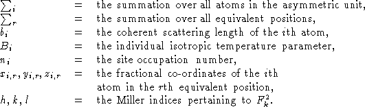
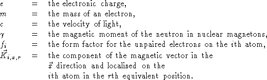
![]()
J. Appl. Cryst. (1969). 2, 65-71.
H.M. Rietveld
Reactor Centrum Nederland,
Petten (N-H.), The Netherlands
Received 29 November 1968
Abstract
A structure refinement method is described which does not use integrated neutron powder intensities, single or overlapping, but employs directly the profile intensities obtained from step-scanning measurements of the powder diagram. Nuclear as well as magnetic structures can be refined, the latter only when their magnetic unit cell is equal to, or a multiple of, the nuclear cell. The least-squares refinement procedure allows, with a simple code, the introduction of linear or quadratic constraints between the parameters.
The powder method has gained a new importance in neutron diffraction owing to the general lack of large specimens for single-crystal methods. Even in those cases where it proves to be possible to grow large single crystals, these may still suffer from such effects as extinction and magnetic domain structures, making a proper interpretation of the diffracted intensities unreliable. Many of these systematic effects are either nonexistent in the powder method, or become isotropic and can therefore be more easily determined.
In a polycrystalline sample it is inevitable that certain information is lost as a result of the random orientation of the crystallites. A further, and in practice more serious, loss of information is a result of the overlap of independent diffraction peaks in the powder diagram. The method of using the total integrated intensities of the separate groups of overlapping peaks in the least-squares refinement of structures (Rietveld, 1966), leads to the loss of all the information contained in the often detailed profile of these composite peaks.
By the use of these profile intensities instead of the integrated quantities in the refinement procedure, however, this difficulty is overcome and it allows the extraction of the maximum amount of information contained in the powder diagram (Rietveld, 1967a). Because of the importance of magnetic structures in neutron diffraction, the refinement method has been made applicable both to nuclear and to magnetic structures. The latter only comprise those structures which can be described on the nuclear unit cell or a multiple thereof.
The neutron powder spectrometer in Petten operates
with a wavelength of ![]() , pyrolytic graphite being
used to suppress the second order contribution
(Loopstra, 1966; Bergsma & van Dijk, 1967). Soller slits
with angular divergences ranging from 10' to 30' can be
installed between the reactor and the monochromator,
and in front of the
, pyrolytic graphite being
used to suppress the second order contribution
(Loopstra, 1966; Bergsma & van Dijk, 1967). Soller slits
with angular divergences ranging from 10' to 30' can be
installed between the reactor and the monochromator,
and in front of the ![]() counter. The monochromator
normally consists of a Cu crystal with its (111) plane
in the reflecting position. The sample is contained in
a thin-walled vanadium tube, approximately 6 cm long
and with a diameter of 1, 1.5, or 2 cm. The maximum
scattering angle is
counter. The monochromator
normally consists of a Cu crystal with its (111) plane
in the reflecting position. The sample is contained in
a thin-walled vanadium tube, approximately 6 cm long
and with a diameter of 1, 1.5, or 2 cm. The maximum
scattering angle is ![]() and the step width usually
ranges from 2.16' to 8.64' depending on the divergences
of the Soller slits. The counter scans through the
diffraction peaks and at each step, at position
and the step width usually
ranges from 2.16' to 8.64' depending on the divergences
of the Soller slits. The counter scans through the
diffraction peaks and at each step, at position ![]() ,
measures a number of counts
,
measures a number of counts ![]() for a preset monitor count.
The background of the recorded diagram is evaluated
graphically at different positions and used to obtain,
by linear interpolation, background corrections
for a preset monitor count.
The background of the recorded diagram is evaluated
graphically at different positions and used to obtain,
by linear interpolation, background corrections ![]() for
each intensity
for
each intensity ![]() . To the corrected intensity,
. To the corrected intensity,
![]() , is assigned a statistical weight
, is assigned a statistical weight ![]() , where
, where
![]() . Because
. Because ![]() is
obtained by graphical means, its variance is not known and is
arbitrarily set equal to zero. With the variance of
is
obtained by graphical means, its variance is not known and is
arbitrarily set equal to zero. With the variance of ![]() from counting statistics equal to
from counting statistics equal to ![]() ,
, ![]() becomes
becomes
![]() .
.
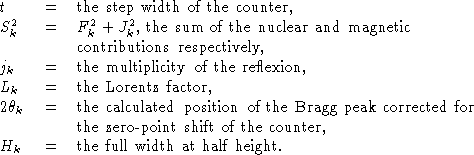
The measured profile of a single powder diffraction
peak is dependent on the neutron spectral distribution,
the monochromator mosaic distribution, the
transmission functions of the Soller slits, and the sample
shape and crystallinity.
While each of these contributions can
have a form not necessarily Gaussian, it still is an
empirical fact that their convolution produces almost
exactly a Gaussian peak shape (Fig.1).
Assuming this Gaussian peak shape for each Bragg
peak, one can now write its contribution to the
measured profile ![]() at position
at position ![]() as
as
![]()
where
Because the absorption of neutrons in the sample is generally negligibly small, no corresponding correction factor has been included in the above expression.
Putting ![]() equation (1) can be simplified to
equation (1) can be simplified to
![]()
At very low scattering angles, however, the peaks begin to show a pronounced asymmetry. This is mainly because of the use of finite slit heights together with finite sample heights. This vertical divergence effect (Klug & Alexander, 1959) causes the maximum of the peak to shift to lower angles, but does not affect the integrated peak area. Introduction of a semi-empirical correction factor in equation (2) gives a good approximation to the asymmetric peak profile (Fig.2):
![]()
where P is the asymmetry parameter and s =+1,0,-1
depending on the difference ![]() being
positive, zero, or negative respectively. As can be seen from
Fig.2, this correction has two main effects: the peak
is shifted to lower angles and the Gaussian peak shape
is made slightly asymmetric.
being
positive, zero, or negative respectively. As can be seen from
Fig.2, this correction has two main effects: the peak
is shifted to lower angles and the Gaussian peak shape
is made slightly asymmetric.
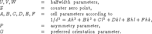
The formula given by Caglioti, Paoletti & Ricci (1958) to express the angular dependence of the halfwidths of the diffraction peaks can be simplified to
![]()
where U, V, and W are the halfwidth parameters. This simple formula also takes account of the peak broadening resulting from the particle-size effect and describes very adequately the experimentally observed variation of halfwidth with scattering angle (Fig.3).
Initial and approximate values for these parameters
are found by graphically measuring the halfwidth ![]() of selected single peaks in the diagram and finding a
least-squares fit to these observed quantities through
equation (4).
of selected single peaks in the diagram and finding a
least-squares fit to these observed quantities through
equation (4).
Plate-like crystallites have a tendency, at least in part of the sample, to align their normals along the axis of the cylindrical sample holder. When this effect is not too pronounced, a condition which is generally fulfilled in neutron diffraction where large samples are common, the intensity corrected for preferred orientation can be written as
![]()
where ![]() is the acute angle between the scattering
vector and the normal to the crystallites. G is the
preferred orientation parameter and is a measure for the
halfwidth of the assumed Gaussian distribution of the
normals about the preferred orientation direction.
is the acute angle between the scattering
vector and the normal to the crystallites. G is the
preferred orientation parameter and is a measure for the
halfwidth of the assumed Gaussian distribution of the
normals about the preferred orientation direction.
Equation (3) can also be written as
![]()
where
![]()
![]() is a measure of the contribution of the Bragg peak
at position
is a measure of the contribution of the Bragg peak
at position ![]() to the diffraction profile
to the diffraction profile ![]() at
position
at
position ![]() .
.
Because the tails of a Gaussian peak decrease rather
rapidly, no large error is introduced by assuming the
peak to extend no further than one and a half times
its halfwidth on both sides of its central position. In
the case of overlap, more than one Bragg peak
contributes to the profile intensity, ![]() , i.e.
, i.e.
![]()
where the summation is over all reflections which can
theoretically contribute to ![]() on the basis of their
position
on the basis of their
position ![]() and their halfwidth
and their halfwidth ![]() . For larger
scattering angles and for crystals with a low symmetry, this
summation can easily be over more than ten terms. On
the other hand, there may be regions of the diagram
where no peaks can possibly contribute and these
regions are therefore left out of the calculations as
containing no relevant information.
. For larger
scattering angles and for crystals with a low symmetry, this
summation can easily be over more than ten terms. On
the other hand, there may be regions of the diagram
where no peaks can possibly contribute and these
regions are therefore left out of the calculations as
containing no relevant information.
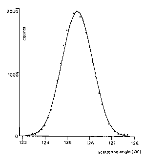
Fig.1. Comparison of a measured diffraction peak, ....., with a calculated Gaussian peak profile, ---.
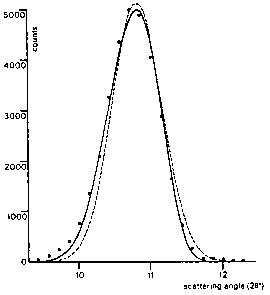
Fig.2. Comparison of an asymmetric diffraction peak with a
symmetric and an asymmetry-corrected calculated profile:
..... measured intensities, - - - symmetric Gauss curve,
--- asymmetric curve.
Fig.3. Variation of peak width with Bragg angle; .....
measured halfwidths,
--- calculated curve.
By writing
![]()
the preferred orientation correction [see equation (5)] and the overall temperature factor are kept outside the expressions for the nuclear and magnetic structure factors. Q is here the overall isotropic temperature parameter.
{
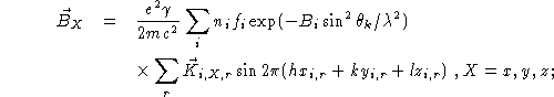
The expression for ![]() can be written as
can be written as
![]() where
where
![]()
and
![]()
The occupation number ![]() for fully occupied lattice
sites is equal to m/M where m is the multiplicity of
the position, special or general, and M is the
multiplicity of the general position in the particular
space group. The value of m ranges in general from 1 to
M.
for fully occupied lattice
sites is equal to m/M where m is the multiplicity of
the position, special or general, and M is the
multiplicity of the general position in the particular
space group. The value of m ranges in general from 1 to
M.
The magnetic coherent scattering cross section can be expressed as
![]()
where ![]() is the unit vector in the direction
of the scattering vector
is the unit vector in the direction
of the scattering vector ![]() and
and ![]() , the magnetic structure factor
(Halpern & Johnson, 1939).
, the magnetic structure factor
(Halpern & Johnson, 1939).
![]() can be resolved into its components:
can be resolved into its components:
![]()
where

The above formulae for the magnetic cross section
are applicable to all magnetic structures with a unit
cell defined by ![]() ,
, ![]() , and
, and ![]() where
u, v, and w are integers and
where
u, v, and w are integers and ![]() ,
, ![]() , and
, and
![]() are the original nuclear unit-cell vectors.
are the original nuclear unit-cell vectors.
The expression (6) is valid for all reflections, equivalent or independent, and can therefore equally well be used with powder or single-crystal methods. In powder diffraction, the number of calculations can be significantly reduced by computing only one average cross section for each set of equivalent reflections (Shirane, 1959; van Laar, 1968). For a magnetic structure with a uniaxial configurational spin symmetry, this average cross section is
![]()
where ![]() is the angle between the unique axis and the
scattering vector
is the angle between the unique axis and the
scattering vector ![]() . The unique axis is assumed
to be the [001] axis.
. The unique axis is assumed
to be the [001] axis.
For magnetic structures with cubic configurational spin symmetry (Shirane, 1959) this expression becomes
![]()
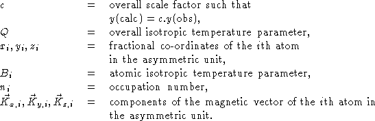
The least-squares parameters can be divided into two groups. The first group, the profile parameters, define the positions, the halfwidths, and the possible asymmetry of the diffraction peaks in addition to a property of the powder sample i.e. preferred orientation. These parameters are
The second group, the structure parameters, define the contents of the asymmetric unit cell:
In order to describe the contents of the complete unit cell, it suffices to give, in addition to the contents of the asymmetric unit, the set of symmetry operations to generate the remaining positions and magnetic vectors in the cell. The symmetry operations on the nuclear positions consist of a rotation and a translation, i.e.
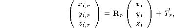
where ![]() and
and ![]() are respectively a
are respectively a
![]() rotation matrix
and a
rotation matrix
and a ![]() translation vector describing the ith
equivalent position.
translation vector describing the ith
equivalent position.
The magnetic vector can undergo a rotation only, i.e.
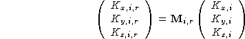
where ![]() is a
is a ![]() rotation matrix
describing the rotation of the magnetic vector of the ith atom on
going from the asymmetric unit to the ith equivalent
position. The subscript i on this matrix indicates that
not all magnetic vectors have to undergo the same
rotation when being transformed to the ith equivalent
position. Each magnetic atom in the asymmetric unit
may therefore have its own set of rotation matrices.
rotation matrix
describing the rotation of the magnetic vector of the ith atom on
going from the asymmetric unit to the ith equivalent
position. The subscript i on this matrix indicates that
not all magnetic vectors have to undergo the same
rotation when being transformed to the ith equivalent
position. Each magnetic atom in the asymmetric unit
may therefore have its own set of rotation matrices.
The principle of the profile refinement method is best demonstrated by the form of the function M which has to be minimized with respect to the parameters. While for the normal refinement procedure on separated integrated intensities this function is
![]()
and on the integrated intensities of groups of overlapping reflections,
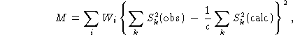
this function becomes, in the case of profile refinement,
![]()
where
A computer program, based on the above described method, carries out the least-squares refinement in the usual manner. Because the problem is not linear in the parameters, approximate values for all parameters are required for the first refinement cycle. These are refined in subsequent refinement cycles until a certain convergence criterion has been reached.
The program provides the possibility of keeping any parameter constant during refinement or of introducing constraints between any number of them (Rollett, 1965; Rietveld, 1967b). The input procedure allows the constraint functions to be either linear or quadratic in all parameters. The latter type of function, for instance, enables the length of a magnetic vector to be kept constant while refinement is carried out on its direction. This introduction of constraint functions, however, increases the size of the, in this case bordered, normal matrix and may lead to possible instabilities in the subsequent inversion when the matrix becomes too large. For very simple linear constraints, therefore, the program allows a substitution method which in effect decreases the size of the matrix.
In order to be able to make some quantitative judgment of the agreement between observed and calculated integrated intensities instead of profile intensities, a fair approximation to the observed integrated intensities can be made by separating the peaks according to the calculated values of the integrated intensities, i.e.
![]()
where
![]()
From the values ![]() one can now obtain values
for
one can now obtain values
for ![]() ),
), ![]() , and
, and
![]() and define the following R values:
and define the following R values:
![]()
![]()
![]()
and
![]()
Over the past year many structures, nuclear as well as
magnetic, have been refined with the method. An
example of a nuclear structure is ![]() (Loopstra & Rietveld, 1969). Its powder diagram (Fig.4)
shows hardly any overlap and the structure may have been
as successfully refined with integrated intensities. The
reason for inclusion of this diagram, however, is the
fact that it demonstrates the nearly perfect fit
obtainable on the assumptions of a Gaussian peak shape
[equation (1)] and a quadratic relation between
halfwidth and scattering angle [equation (4)].
(Loopstra & Rietveld, 1969). Its powder diagram (Fig.4)
shows hardly any overlap and the structure may have been
as successfully refined with integrated intensities. The
reason for inclusion of this diagram, however, is the
fact that it demonstrates the nearly perfect fit
obtainable on the assumptions of a Gaussian peak shape
[equation (1)] and a quadratic relation between
halfwidth and scattering angle [equation (4)].
The powder diagram (Fig.5) of ![]() exhibits
severe overlap. At large angles, more than ten
reflections may contribute to a profile intensity. While the
information content of this part of the diagram is low,
the agreement between observed and calculated
profiles shows that even this amount has been used to the
fullest extent.
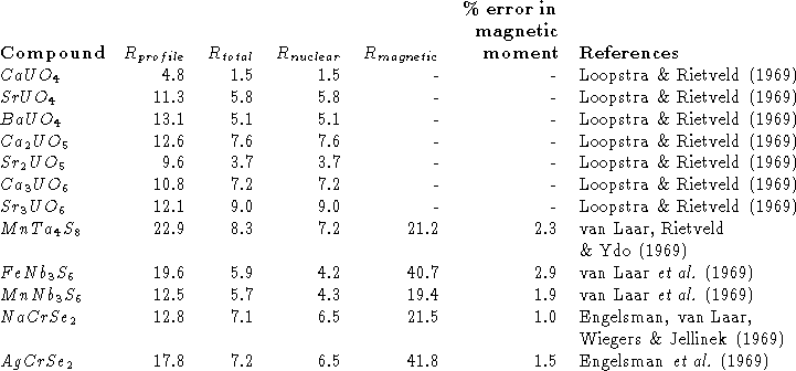
Some of the other structures are shown in Table 1
with their R values. The large
exhibits
severe overlap. At large angles, more than ten
reflections may contribute to a profile intensity. While the
information content of this part of the diagram is low,
the agreement between observed and calculated
profiles shows that even this amount has been used to the
fullest extent.
Some of the other structures are shown in Table 1
with their R values. The large ![]() values in
this list are caused by the fact that the nuclear scattering
generally overrides the magnetic contributions, making
the above-described method of separating peaks
[equation(7)] very unreliable for these magnetic intensities.
This, however, does not indicate that the magnetic
moments found by this least-squares procedure suffer
from the same inaccuracy, their relative statistical
errors being in the range of
values in
this list are caused by the fact that the nuclear scattering
generally overrides the magnetic contributions, making
the above-described method of separating peaks
[equation(7)] very unreliable for these magnetic intensities.
This, however, does not indicate that the magnetic
moments found by this least-squares procedure suffer
from the same inaccuracy, their relative statistical
errors being in the range of ![]() . It only
demonstrates the potential of the method for extracting the
maximum available information from a powder
diagram as opposed to any peak-separation method. It
may also be remarked here that an increase in the
resolution of the diagram, while of no use in
peak separation methods if it does not produce separable
peaks, is always profitable in the profile method
because it results in a higher information content owing
to increased detail in the profile.
. It only
demonstrates the potential of the method for extracting the
maximum available information from a powder
diagram as opposed to any peak-separation method. It
may also be remarked here that an increase in the
resolution of the diagram, while of no use in
peak separation methods if it does not produce separable
peaks, is always profitable in the profile method
because it results in a higher information content owing
to increased detail in the profile.
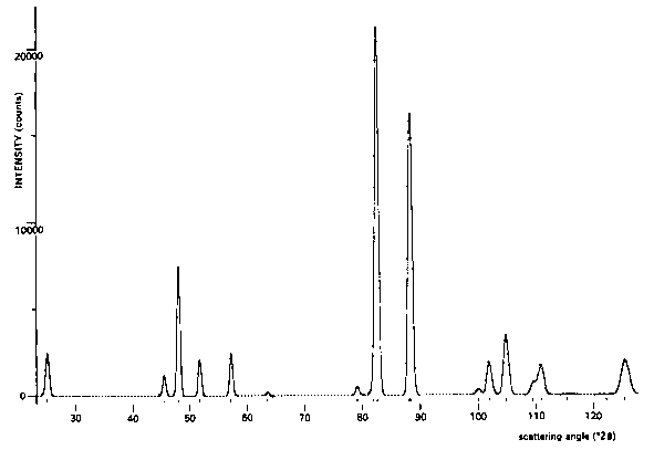
Fig.4. Neutron powder diffraction diagram of ![]() measured at
measured at ![]() ;
;
--- calculated profile, . . . . measured profile.
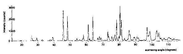
Fig.5. Neutron powder diffraction diagram of ![]() measured at
measured at ![]() ;
;
--- calculated profile, . . . . measured profile.
Table 1. R Values of various nuclear and magnetic structures.
The least-squares refinement program has been written in Algol 60 to be run on an Electrologica X-8 computer having 48 K words (26 bits) core storage and magnetic tape units. Because of the necessity of comparing graphical data in the form of calculated and observed diffraction diagrams, instead of the usual integrated intensities, extensive use is being made of an automatic incremental plotter.
A detailed description of the program can be obtained from the author (Rietveld, 1969).
In all instances the profile refinement procedure has proved to be superior to any other method involving either peak separation or the use of the total integrated intensity of groups of overlapping peaks. It is felt that in this way one of the inherent drawbacks of the powder method, i.e. the loss of information as a result of overlap, has been effectively overcome and that the method in many instances can now compete with single-crystal methods, especially when these are subject to systematic errors.
The method can in principle also be extended to X-ray powder diagrams, if a satisfactory function can be found to describe the peak profiles. However, the method will remain best suited for neutron powder- techniques because of the nearly exactly Gaussian shape of the diffraction peaks and the possibility of describing the variation of halfwidth with Bragg angle in terms of a simple quadratic function.
The author wishes to thank Drs B.O. Loopstra and B. van Laar for their suggestions and helpful criticism.